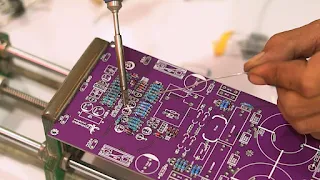
High Power Amplifier Class-D D2K5 Fullbridge Dual Feedback
Elcircuit will assemble a class-d D2k5 dual feedback power amplifier, this This power amplifier is a high-power power amplifier, can be supplied with a symmetrical 90VDC voltage, with a power output of up to 2800W RMS. This D2K5 Fullbridge amplifier can be used for 18-21inch subwoofer speakers. the scheme was designed by Mr. Katino Surodipo.
I've previously made this SMD version of the D2K5 amplifier. The SMD version is more difficult to assemble because the small components are small. But in this post, still uses single feedback, namely prefilter feedback.
Because friends are enthusiastic about assembling using DIP components or normal components, I made a version of ordinary components without using SMD components.
The features are still the same as the SMD version, but for the OCP I used the latest version of OCP using transistors, previously using NE555.
And the following is the PCB layout, a PCB with a dual-layer design.
PCB Layout Power Amplifier Class-D D2K5 Fixed
The dimensions of this PCB are 9.5cm wide and 28cm long. In the signal section, I design using arc angle paths and not wide using 0.3-0.5mm, so that there is less noise or hum because it is covered by grounding, which is more optimal. For those of you who want to buy the PCB layout, you can chat via WhatsApp at the end of this post.
 |
| New Soldermask PCBWay |
We first assemble the D2K5 Fullbridge Dual Feedback amplifier, prepare the components first, use quality components, and don't bargain for the value, because the quality and value of the components greatly affect the performance of the amplifier, not just Class-d Amplifier, all amplifier classes are the same.
Part Class-D Fullbridge D2K5
We first install the components according to the label on the PCB. I put the resistor and diode first.
Solder the components, we can also solder the components directly from above like this.
Lack of soldering from above like this, the traces of the solder will be visible and can be cleaned using a thinner. However, you have to be careful if you use a resistor of poor quality, usually, the color of the bracelet will also disappear if it is exposed to thinner.
Before installing the capacitor, I will first install the TL072 Input balance opamp IC and the TL071 comparator.
for bootstrap diodes I use 2 RL2 diodes and 1 MUR460.
The LPF capacitor I use is 1.5uF 250V
For the inductor, I use a core with a diameter of 4cm, with the MS 157060-2 series as much as 1 piece per side, this can also be doubled, and it's better than using a single core. I used 2 double 1mm wire, wrapped around 21 turns. Its inductance value is about 40uH. If you use a double core, the number of turns is 17 coils.
Core Inductor Class-D D2K5 Fullbridge
Tin it on the exposed silkscreen layer or on the bottom soldermask, so the path is stronger, and lasts longer.
Mosfet Class-D D2K5 Fullbridge
The mosfet that I use is 4 IRFP260 mosfet, and can also use other N Channel mosfet, for example IRFP250, IRFP4227, IRFP4229, IRFP4242, IRFP4332.Install the heatsink, the heatsink I use is 9.8cm wide and 30cm long. Don't forget to put an insulator on the mosfet, and also give thermal grease so that the heat is evenly distributed to the heatsink. And for the PCB spacers, use the 5mm one, so that it fits and is even.
Amplifier D2K5 kit is ready and ready to be tested
You can watch the Amplifier test in the following video: Class D D2K5 Fullbridge
For those who want to buy PCB Layout with Gerber file format, buy it via WhatsApp click link below:
.jpg)


bagus mas ,
ReplyDeletemohon info untuk harga PCB Layout with Gerber file format
This comment has been removed by the author.
DeleteIs the updated schematic shareable if so may i see it
ReplyDeleteI build this amp, why there is breek breek sound when i turn in 9 o'clock up, i use supply 95vdc.. please help me thnks
ReplyDeleteTry change R56 and R58 to 220K 1/4W
DeleteTry change R56 R58 to 220K 1/4W
DeleteAnyone can help me?i need the list of Part need to change in d3k9 for 130vdc supply,
ReplyDeleteyou can search on youtube
DeleteI need to run it at +-140vdc, please guide which components needs to be replaced? As i cannot understand indonatian language i couldn't understand from video
ReplyDeletefor +70 0 -70VDC you mean?
Delete+70 -0 -70V you mean?
Deletehow many speaker 350 rms ohms can be load for this amplifier.
ReplyDelete