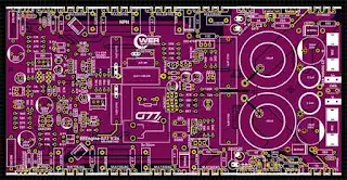
PCB Layout TD EEEngine G77 PSU 160V DC CT
High Power Amplifier Class TD EEEngine , EEEngine G77 high voltage power supply upto 180VDC CT power output up to 2500W RMS.
Here's the PCB layout that I designed, this PCB can be downloaded at the link in the description. the holes for the tr final buffer and MOSFET I made are similar to castellated. But here I add these small through holes to make it stronger and when I remove the final tr until the copper layer is peeled off, these small through-holes are used as a backup for the connection between the top and bottom layers. so we don't have to bother soldering the transistor from the bottom.
For this 2.2uH air-core inductor using a 1.5mm wire wrapped around 24 loops of 2 loops, with an inner diameter of 8mm, I wrapped this using a drill bit with a diameter of 8mm, the method of winding it was 2 loops, the direction of rotation of the windings is free, but if possible, the direction of the winding is the same. between the inductors. For the buck step-down inductor, the core I use is the MS130125-2 core, because the place is too tight, I use 2 double 1mm wires, and it is wrapped 28 times, the direction of the winding between the inductors may be different, but it's better to be in the same direction.
For the Zobel RL, the inductor I use is a 1.5mm wire wrapped around 14 turns, and the resistor I use is R 10ohm 5 Watt.
For this servo bias tr, I use a jumper cable to attach it to the final tr or to the heatsink. A transistor can be replaced BD139 or MJE340.
Final transistor can use MJL21193 / MJL21194
Download
Gerber files buy here: PCB Layout Gerber Files EEEngine G77 FIXED 100%
.jpg)

This circuit works , i tried. Thanks for sharing.
ReplyDeleteReally nice
Deleteits work bro
DeleteTransformer need for max output
ReplyDeleteHey, could you send me the electrical scheme? luizcpimenta @gmail.com
ReplyDelete