1000W Discrete UcD Class-D Superlite
Hello friends, on this occasion I will post again, the discrete class-D amplifier UcD Superlite,
Class-D Discrete Amplifier UcD Superlite with RM Core
Is that a discrete class-d UcD?
UCD is one of the Class D Topologies patented by Philips (NXP) and this Class D type is widely used in Hypex products which they claim can compete with Class AB power.
and class-d discrete is a class d power circuit without using IC eg MOSFET IR2110 driver or logic inverting, so it only uses capacitor resistors and transistors, but in this Superlite uses 1 dual OP-AMP IC used for the balanced input for easier reasons sought and many variants rather than discrete op-amps.
UcD Superlite was designed by Indonesian audio experts, Mr. Kartino Surodipo, who is also the admin in the Class-D Next-generation amplifier Indonesia group, he shares a lot of knowledge and design of amplifiers for free or free.
This amplifier, in my opinion, this bass sound is more punch and soft, with a standard MOSFET and PWM freq 250khz, Mid and high sound is also pretty good, it can crisp.
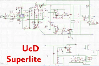
Ripple output or residual PWM can be very low, so it is very safe for Twetter, not easily broken, and here I will design the PCB with a macro component, the following UcD power amplifier scheme which I re-schema in the EasyEDA application.
Complete circuit
- Input balance
- DCP, Speaker protector which functions to disconnect the relay when the speaker output DC voltage is at least 2V
- Led Indicators, there are ON, Signal, Protection Clip, and ready.
- 60VDC-95VDC PSU range.
- For the power output ... we will immediately test it using measurements using Oscilloscope, Ampere Pliers, Avometer, and Dummy load. So it is not difficult to set hundreds or even thousands of watts without measurement.
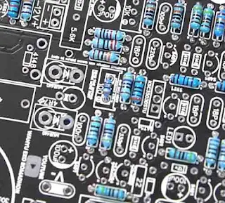
The PCB Layout that I designed myself, in dual-layer, the dimensions of the PCB are 10x10cm. very compact size and also efficient for the use of power 4 channels, the component looks very tight yes, it is still very safe not to be disturbed for the input signal with PWM oscillation signal, the gap or the distance of the pad is still far compared to me using the SMD component.
for component values do not be negotiable for class D power, because the slight difference will affect the PWM, stability and switching frequency, this is very influential with the sound and power output of class D amplifiers.
For the PWM Cap freq value I use 220pF multilayer capacitors, dual opamp ICs for Inbal using Low Noise MC33078 SMD op-amps can also use DIP version, dead time resistors use 300 + 39ohm 1 / 4W, comparator uses 2n5551 and C3503 manufacturers ON semi, bat54 diodes using SMD, TR Totem using C2655 and A1020 pairs, for dumper diodes using ES2D or can also use Mur240 or ultrafast 2A diodes, MOSFETs using IRFP260N 2 seeds.
 |
| Resistor Dead Time Set |
 |
| C3503 (ON Semi) 2N5551 (Philips) |
For Inductor LPF I use several core variants, but for this post, I use MS130 core 3 cm with an inductance value of 33uH. LPF cap 1uF 250V. The relay uses a 12V 20A relay.
 |
| Core MS-130060 3.3cm diameter |
I use a heatsink aluminum plate with a thickness of 4mm is enough for a class D amplifier. One of the advantages of class D amplifiers compared to other classes is that the efficiency is very high, up to 90% or even more. So the power wasted by heat is so minimal that the heat sink or cooler can be smaller than class AB. Then why is there class D that still uses a fan? yes because there is still power wasted by the heat of about 10%, so suppose this amplifier is branded with 1000W of power then 10% of power is wasted around 100W if discharged by heat, this exceeds 60W solder heat, you can imagine for yourself how hot the 60W solder. So it is better to install a fan, other than that DCO or PWM will be more stable if the temperature of the active component is stable, not hot.
 |
| Heatsink 105mmx100mm |
The UcD kit is ready and ready to be tested, I use a 90VDC voltage for the main PSU, with the bias I took from the SMPS, note that the SMPS already has a special voltage for bias, the bias voltage must be separate from the main supply or other accessories. Potentiometer uses 10k ohm mono.
For the load test, I installed the output to a 4 ohm 1000W dummy load, and also the measurements that I have installed to measure the output voltage and current, DC output, the temperature of the heatsink amplifier, and also to the watt meter AC input.
 |
| 700W Power Output at 90VDC Symmetrical PSU, Signal 1kHz |
Full video making and test:
New UcD Superlite
.jpg)


please check, when i click to download it is directing to the contact page
ReplyDeleteplease check again
Deleteyou can download PDF
ReplyDeleteLink for schematic pdf? Dont see
ReplyDeleteShare the schematic in good quality and the list of components. Thank.
ReplyDeletePlease upload components list
ReplyDeleteyou can find it in bom files
Deletethere is no bom file in zip on gdrive (placed link in article)
DeleteHello. Please add a diagram in good quality and, if possible, a list of components. I will be very grateful for your help.
ReplyDeleteWhere can i download the other version
ReplyDeleteisn't have a schematic pdf in google drive.
ReplyDeleteI have a PCB on JLCPCB, but doesn't have a BOM and SCHEMATIC.
please! can you gave a pdf for finding some missing labeled components on PCB.
Thank You!
Can you please tell me the number or RM core .....
ReplyDeletehello. there is no bom file and cheme at your link. plese fix this. thank you
ReplyDelete