1200W Power Amplifier Crown XLS 1200
This time I will share about power amplifier circuit Crown XLS x6FT, where this power amplifier can be produced 1200W RMS. This power amplifier Crown XLS x6FT can be supplied with a voltage of at least 45V DC to 90V DC, and to get maximum power you can use a Power supply with high voltage and current. For example, using 75V 20A. Final Transistor power amplifier using 6x 2SC5200 / 2SA1943. Below you can see the schematic power amplifier.
Crown XLS schematic power amplifier
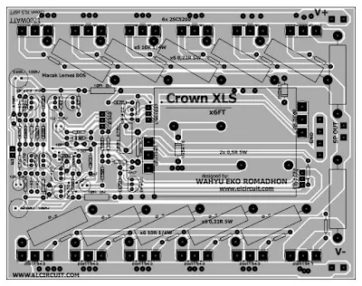
PCB Layout Crown XLS power amplifier 2 Layer
Finished PCB Power Amplifier Crown 1200W
Troubleshooting in component installation, consider the image below:
Explanation of number labels:
1. You can use a non-polar 10uF / 25V capacitor or polarized capacitor in series 22uF + 22uF and attach the foot + to the PCB
2. Same as number one, but if you use a series polarized capacitor that is 2u2F + 2u2F and attach the foot + to the PCB,
3. Resistor 1/4W 470R 5% Tolerance
4. Use the MUR120 diode or you can not use the diode.
5. Resistors installed at the bottom, ie 2x470R / 2W instead of 2x0.5R 5W.
Download
Schematic + PCB Layout design Power Amplifier Crown XLS.RARPCB GERBER FILES
https://www.pcbway.com/project/shareproject/High_Power_Amplifier_Crown.html
.jpg)


great article
ReplyDeletenext will be updated power amplifier
Deletecan you send me the components that u used? and that power supply u have? i wanna try it for the first time.
DeleteThis comment has been removed by the author.
ReplyDeleteFile conrrupt
ReplyDeletefor gerber?
Deletelink is corrupt Schematic + PCB Layout design Power Amplifier Crown XLS.RAR
ReplyDeleteTry to download gerber files. And password elcircuit.com
Deleterecieved your PCBs, I ordered for the Crown XLS.....need a parts list, very hard to read schematic, also PCB is missing some component details, please respond, or, I will contact JLCPCB, and request a refund , I have messaged you on different forums many times...NO RESPONSE..this the PCBs I ordered.......I am very angry.....https://www.pcbway.com/project/shareproject/High_Power_Amplifier_Crown.html
ReplyDeletePlease provide the list of components used in this amplifier circuit
ReplyDeletehello friend I'm from Colombia and I liked your work, but you can do me the favor of passing me the list of the components and the measures of the card I would appreciate it.
ReplyDeleteyou can see the schematic
DeleteFile RARnya rusak om
ReplyDeleteI have a small problem with this. IF you are using 90V, the total allowed current per transistor is 600mA. It means total ~7Ampers on the output. This is so far from the 1200Watts. On 4Ohms it would require 17Ampers on the output, and in case of 8Ohm 12Ampers, but a lot higher voltage. This amplifier could handle only about 600 - 640Watts. For maximum 10ms with non-repeative pulse, it can deliver 1200Watts. I don't really understand how you calculated the 1200Watts, but 6 pair of 2SC5200 / 2SA1943 could not deliver this amount of power. I recommend to check the Power-Derating curve and SOA (Safe Operating Area) charts of these transistors, before you've been surprised by some smoke that comming out from the transistors and your speakers. http://pdf1.alldatasheet.com/datasheet-pdf/view/245448/FAIRCHILD/2SC5200.html
ReplyDeleteVery true
DeletePLZ CONTECT ME 03014502581
ReplyDeleteThis comment has been removed by the author.
ReplyDeleteMy friend, you evidently do not like my comment about errors in your circuit??? These errors are caused by your complete ignorance of the principles of power amplifiers. You created a completely non-functional hybrid of several circuits. This scheme is not viable.
ReplyDeleteI got your PCB, and then I just threw it in the trash. I'm not going to waste time spoiling the transistors on your illiterate development, fit only to lie in a landfill. And believe me, many competent radio engineers will do the same as I do.
ReplyDeletesir pcb board size plz
ReplyDeletein 1 ohm will work?
ReplyDeletenot recomended
Delete