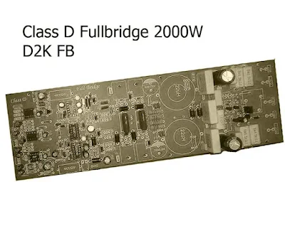
Power Amplifier Class-D Fullbridge D2K 2000Watts
This is high power amplifier circuit with Class-D system fullbridge which has a power output up to 2000W RMS with the voltage about 90VDC Symmetrical Power Supply (Recomended using Switching Mode Power Supply). Audio Class D amplifier is basically a switching-amplifier or Pulse Width Modulation-Amplifier. A class D audio amplifier has 90% efficiency when the speaker is loaded. While theoretically the Class D audio amplifier has an ideal efficiency of 100%. This Class-D Fullbridge Power Amplifier schematic is originally designed by Mr. Kartino Surodipo. Below the schematic circuit design and PCB Layout Power Amplifier, if you want the PDF file you can download at the links on attachment.
Schematic Design:
PCB Layout Design:
Final Mosfet Transistor N-CHANNEL IRFP4227:
For the Final Mosfet Transistor you can buy here its TRUSTED by click this link : BUY IRFP4227
Project Power Amplifier Class-D Full Bridge 2000W D2K:
Video Tested Power Amplifier By Mr
Download PDF Files Schematic and PCB Layout for Larger view:
- D2K Fullbridge Schematic Diagram.pdf
- Component Design PCB Class-D Amplifier D2K.pdf
- PCB Layout Class-D Power Amplifier D2K.pdf
.jpg)


Can you tell who is make the clas d amp design?
ReplyDeletemr. kartino surodipo
Deleteyou can see at the link Mr.Kartino Surodipo facebook. He is creator and design it. If you want to get more info u can tell with him.
ReplyDeletealready tested ?
ReplyDeleteyes its tested and works properly for class d amplifier.
DeleteI had tried not working.
Deletehi is it possible to write the parts we need to make this amp
ReplyDeleteits hard to find it one by one from the pdf you uploaded.
thank you.
just write or post it like the other project as a list (parts will need)
ReplyDeleteOkay sir i will contact my friend as post writer to update the part list, thanks for your suggestion.
DeleteHope you enjoy in my site!
Help me. What is plugged into the bias connector?
ReplyDeleteWhat to connect there?
DeleteYou must plug a 12 v regulated supply.
DeleteIt is only one board 2000w or both
ReplyDeleteits only one board 2000Watt
ReplyDeleteHello,
ReplyDeleteI tested this version of pcb...and wont start. Sometimes start only one side of amplifier. Can tell me if someone already tested this version and work?
what the voltage of your power supply bias?
DeleteIf i want not use bias point what can i do
ReplyDeleteyou must using bias voltage,
DeletePower supply voltage around 100v from ground
ReplyDeleteWhere connect the bias point tell me
ReplyDeleteat the 12V power suply
DeleteExternal or
ReplyDeleteHe bro i made this pcb but there have lots of bugs in pcb layout
ReplyDeletecan u tell me the bugs?
DeleteHi, can i get less power using a lower voltage? tanks, it looks so good bro!!
ReplyDeleteyes you can get a lower voltage but less output power.
DeleteOnly low sida pulse are working high side is off
ReplyDeletecheck again with your ir2110
Deletenot working PCB,please update
ReplyDeletehttp://www.diyaudio.com/forums/class-d/301218-fullbridge-class-pa-ultra-power-12.html
Hello brother pls tell the size of pcb
ReplyDeleteHello brother pls tell the size of pcb
ReplyDeletePcb not working for me no output
ReplyDeletePcb not working for me no output
ReplyDeleteBad circuit not working. Is wasthere of funds.
ReplyDeleteSir plese make garbar files
ReplyDeleteShift_L
persamaan fetnya nomer seri IRFP4227 apa ya gan
ReplyDeleteThanks sir
ReplyDeleteCan anyone explain what are all the benefits for D2K Fullbridge.
ReplyDeleteCIRCUTE DIAGRAM AND PCB DIAGRAM ARE DIFFERENT
ReplyDeletePCB DIAGRAM NOT SHOW 555 TIMER IC BUT THE CIRCUTE DIAGRAM IN 555 IC Why?
amigo ya lo hice y funciona ala perfeccion
ReplyDeleteThis PCB has many errors. Don't try this.
ReplyDeleteive tested this amp the updated one with diy pcb and its working fine..theres a little bit tweek in the SD of ir2110..
ReplyDeleteHey carlos excuse my english.
ReplyDeleteyou do not know whether pcb this amplifier is an functional.
The last functional pcb model is an this ?
No funciona crei que funcionaba
ReplyDeleteGuys have anyone got any positive result for this pcb. Whether working or not...?
ReplyDeleteI screwed it up can help me
ReplyDeleteHi can i access the full list of components thank you
ReplyDeleteGracias por los archivos
ReplyDeleteYoure wellcome
DeleteHa ha..
ReplyDeleteI tried it.
https://www.youtube.com/watch?v=GOs7gY3F7rM&ab_channel=GeneralDiy