Parametric Tone Control IC4558 and PCB
How to Make a Parametric Tone Control IC4558. Tone Control is an electronic circuit to set the tone or process so pleasant to hear. Tone Control is usually present only a 3 to 4 setting only, namely:
• Volume
• Bass
• Treble and
• Mid (Vocal)
Tone Control process the voice signal from the MP3, Phone output, DVD, Laptop or the other device. and then the results of the processed or the output of the Parametric Tone Control, Parametric Tone Control will be forwarded to the Power Amplifier that the processed sound Parametric Tone Control to be great. If you have not got his Power Amplifier please search here Power Amplifier Circuit, see circuit diagram below
Parametric Tone Control IC4558 Circuit Diagram
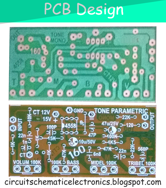
To increase the quality Passive Tone Control this we must add the Tone Booster, Turbo Bass, Subwoofer module or another pre-amplifier circuit so that the sound that produced Parametric Tone Control to be as original sound or even louder and powerful output. For PCB Layout Design see image below.
PCB Layout Design Parametric Tone Control
For power supply circuit using regulated power supply using IC 7812 or 7815. Because this Parametric Tone Control need voltage supply about 12V to 15V DC,
Project 4558 Tone Control Circuit by Guest elcircuit:
Project 4558 Tone Control Circuit by Guest elcircuit:
.jpg)


where?
ReplyDeletewhat its ?
DeleteThis comment has been removed by the author.
ReplyDeleteThis comment has been removed by the author.
ReplyDeletei made one..and it works..its super perfect design..thanks sir..
ReplyDeleteby the way i replace the cap 22n into mylar .022 because here in philippines no available of 22n and the 6n8 i replace it into mylar .001 and it works perpect
ReplyDeletethanks again sir..
hello jame,
Deletethank you for your interesting circuit. And congrat for your dine project. Can you send me your project?
you mean my finish project?
ReplyDeleteyes i will
DeleteHello Jaime ... Could you help me by answering the question I ask below? ... It's about the "CT" connection ... I do not know what it means nor the function it performs.
I would appreciate a diagram that you have tried and if you can send me to [email protected]
Thank you my friend
yes jame.. your finshed project. you can contactme at [email protected]
ReplyDeleteHi. Sorry but I do not understand what type of connection is "CT" and what pin the potentiometer of columen is connected .... Thanks for answering, very good project ... I hope to do it
ReplyDelete0V /gnd
DeleteCT MEANING PLEASE GIVE THE MEANING OF THAT
ReplyDeleteCT means "common transformer" This uses 12 volts common transformer.
Deleteyes 0/gnd
Delete