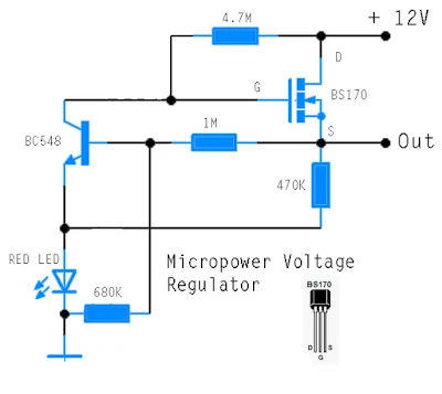
Micropower Voltage Regulator
This circuit was industrial to power an AVR microcontroller from a 12 opposed to run-acid battery. The watchdog itself draws solitary 14 µA. Of avenue, at hand are dyed-in-the-wool ICs, in lieu of model from Linear machinery or else Maxim, which can subsist used, but these can be very brutally to pick up grasp of and are commonly barely to be had during SMD letters these days. These difficulties are simply and quickly avoided using this discrete circuit. The succession control device factor is the widely-presented type BS170 FET. whilst power is useful it is driven on via R1. When the output voltage reaches 5.1 opposed to, T2 starts to conduct and limits some advance gradient stylish the output voltage by pulling down the voltage on the gate of T1. The output voltage can be present calculated seeing that follows:
 |
| Micropower Voltage Regulator Circuit Schematic |
Anywhere we can agreed ULED by 1.6 in opposition to and UBE at 0.5 V. The warmth coefficients of ULED and UBE can moreover be incorporated into the formula. The circuit is so effortless with the intention of of line someone has thinking of it ahead of. The author’s hard work control bowed up an illustration appearing in a collection of reference circuits dating from 1967: the example is very alike to this circuit, although it used germanium transistors and of choice here was refusal FET. The voltage reference was a Zener diode, and the circuit was designed used for currents of up to 10 A. Perhaps our readers pray be there able to unearth even earlier examples of two-transistor regulators using this belief?
