Inverter 12V to 115V with 25 W power output
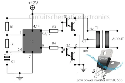
Low power inverter schematic are only use 9 components , one of which IC 556 , TIP120 NPN Darlington transistor.
And turns 10 to 16 Vdc into 60 HZ, output 115 V square-wave power to operate ac equipment up to 25 W. In the circuit first ic originally hires as a timer chip m for stabilizatiom oscilator with components R1 and C1 setting frequency oscilator. Then the two transistor driver, drive the transformer push-pull fashion, When one transistor is biased on , the other circuit cut-off . The transformer is a 120V/18Vct unit that is connected backwards, so that it steps the voltage up rather than down. Oscilator circuit operates from about 4 to 16 V for stable output.
And turns 10 to 16 Vdc into 60 HZ, output 115 V square-wave power to operate ac equipment up to 25 W. In the circuit first ic originally hires as a timer chip m for stabilizatiom oscilator with components R1 and C1 setting frequency oscilator. Then the two transistor driver, drive the transformer push-pull fashion, When one transistor is biased on , the other circuit cut-off . The transformer is a 120V/18Vct unit that is connected backwards, so that it steps the voltage up rather than down. Oscilator circuit operates from about 4 to 16 V for stable output.
Part List :
R1 = 1K
R2 = 12K
R3 = 1K
R4 = 1/4W
C1 = 1uF
IC = 556
Q1 = TIP120
Q2 = TIP120
T1 = 120V 18VCT
.jpg)

Post a Comment for "Inverter 12V to 115V with 25 W power output"
Dont use outgoing links!