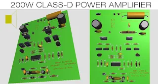
200W Class D Power Amplifier IRF540/IRF9540
 |
| Class D Switching Power Amplifier Project |
Related to the power of an AB class amplifier is categorized as efficient in power usage, but the heat absorption requirements are still large.
This is because the final transistor is not employed until saturation conditions, where the lowest heat dissipation occurs when the transistor is fully conducting (saturated) or does not deliver at all. In class AB, the transistor varies the current/voltage current (according to its input waveform), residing in this state, each working half its wave cycle, thereby even though the efficient heat absorber required to cool the transistor must remain large.
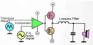
If a sine voltage is matched by a comparator circuit with a triangular signal, the discharge voltage is a series of pulses whose width varies according to the high input voltage of the sine. During the positive parts of the audio signal, the pulse is widening and narrowing in the negative period. This pulse is then used to drive a power transistor in a condition on or off completely. This is the basic principle of class D amplifiers work.
A series of pulses of the order of hundreds of kilo hertz of modulated width is used as a carrier of audio signals and passed through an amplifier. To recover the original waveform, it only takes a low-pass filter like a passive crossover circuit belonging to the mid-to-low range speakers. This filter skips variations of slow audio signals to be forwarded to the speakers and muted carrier signal frequency.
 |
| Basic Circuit of Class D Amplifier |
Hence the modulation can be made very linear, the distortion number of the amplifier can be lowered. And because heat scattering is minimal, it takes a small heat sink. The main advantages of the class D amplifier are much more compact dimensions, lighter and cooler than conventional amplifiers with the same output power.
While the benefits side audio quality, output class D amplifier is well known for a fast dynamic response so that a strong bass kick will be able to be reproduced with a more agile but stable and very powerful.
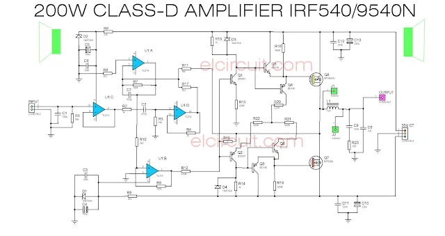
After getting a little familiar with the working principle and the advantages of class D amplifiers, I will share and let's create a class D power amplifier circuit with 200W power using IRF540N and IRF9540N MOSFET transistors. And driver circuit using transistor BD139 / BD140, 2N5401 / 2N5551. For comparator circuit use op-amp IC TL074. Here's the circuit diagram of 200W Class D Power Amplifier:
The circuit is a series of mono power amplifiers, which can produce 200 Watt at 8 Ohm Speaker. If you make this stereo power amplifier it can produce 2x200W or 400W output power.
For the power supply voltage, you can use 35V-55V DC CT circuit, use this Symmetrical Power Supply Circuit for this Class D amplifier.
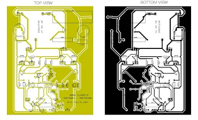
To simplify making this class d amplifier I also share the following layout PCB Layout:
 |
| PCB layout drawings are original routing of the circuit schematic diagram above. |
 |
| You can buy this KIT Power Amplifier by visit this link: Dios 200Watt Class D Amplifier. |
Video Test 200Watt Class D Amplifier
Class D Amplifier is Compact, Powerful, Low Cost, High Efficient.
.jpg)


what the value of inductor L1?
ReplyDeleteThe inductor L1 is 10mH , or you can use inductor from low pass filter passive crossover.
ReplyDeleteparts list please
ReplyDeleteSee the lastest post about D200W Class D on elcircuit.com its complete.
ReplyDeleteNot working. Bad amplifier
ReplyDeleteits working sir
DeleteI have build 2of these ...one is is keep putting dc on output, and artea i unplug it from mains is working for 2seconds, the other is ffuzzing on the output and burns the 220 ohm resistor on the negative side of the bd140, lower side. I replaced the semiconductors twice on both of them. Still the same. On the oscilloscope everything fine on the gates
ReplyDeleteThank you for sharing the circuit. I will have a go at building the circuit but the parts list is unclear from the diagram. Could you please give a better view or a pdf file. Also, any idea of the distortion? Thanks and regards. [email protected]
ReplyDeleteHow can i download the gerber of this amplifier
ReplyDeletePdf provides
ReplyDelete