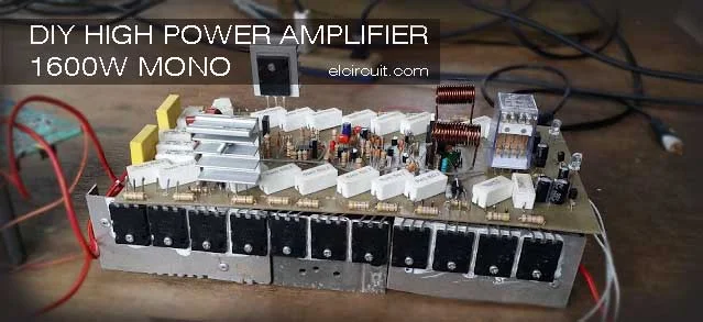
1600W High Power Amplifier Circuit complete PCB Layout
This power amplifier circuit is a 1600W at 8 Ohm mono circuit that uses transistors as an amplifier. Almost same with 2800W high power amplifier circuit, For stereo power amplifier circuit, you can use this circuit 2x and will issue a power of 3200W. Let us first see the circuit schematic below.
1600W High Power Amplifier Circuit Diagram
In the buffer circuit coupled with op-amp ic 4558, supplied 15VDC voltage, circuit power supply you can see in the picture is flavored transistor D313 and B507. Driver circuit using transistor MJE340 MJE350. For use transformer, it's using one transformer by one circuit mono. CT of the transformer is not connected to the ground, will be a short-circuit. Due to this 1600W power amplifier circuit just use a plus and minus voltage only.
PCB LAYOUT for 1600W high power amplifier circuit
DIY 1600W High Power Amplifier Project by Guest elcircuit Facebook Fanpage: Junjun Mojendar
Video Test 1600W Power Amplifier Circuit:
The Power amplifier using final transistor 2SA1943 and 2SC5200 12 Set, for more powerful output amplifier using an original transistor. You can see the PCB Layout transistor as many as 12 sets by channel (Mono Amplifier) in order to issue a power of 1600W or 1,6kW at supply voltage 65VDC.
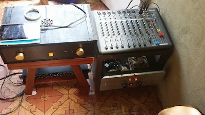
Below Updated the power amplifier builds completed and tested see the image and video:
 |
| The speakers used 15"x2 12"x2 2x tweeter |
 |
| 1600W Power Amplifier Completed |
High Power Amplifier Project by Jun Modenjar
.jpg)


what the amperage the transformer for power amplifier?
ReplyDeleteyou can use 10A transformer or greater
DeleteIf iam use 5A transformer, what the impact?
Deleteit less current voltage.. so the power amplifier output give less power . so it can affect for speaker used.
Deletecan i use 1/4 watt for resistor?
ReplyDeleteyes you can use it for the driver, buffer,and speaker protect circuit.
ReplyDelete1600W ??? on what kind of load?
ReplyDelete8 ohms load
DeleteCertainly NOT with 65V rails.
Deleteobvious bad pcb layout for those outputs, their legs far from straight. needs a lot of work to make this layout better.
ReplyDeleteyes it so difficult to make this layout. but its tested amp and powerfull sound output.
DeletePlease send me the Proteus file. My email is [email protected]
ReplyDeletei dont have the proteus file sir.
DeleteSir can you send me pcb layout diagram and parts list pls...
ReplyDeleteThanks in advance
[email protected]
please click the image to see it clearly
DeleteKalo Beli PCB nya dimana mas..? harga berapa..? atau file design PCB nya.. makasih
ReplyDeleteIni bli di madiun bnyak mas.
DeleteAd mas pcb dan skema d saya
DeleteWith ± 65V rail, that's equal to about 46V RMS. With 8 ohms load, that should be about 265 watts & not 1600 watts
ReplyDeletehello.. it is about maximum power.. not only calculating the power supply input and output. you can supply max voltage up to 100v dc
Deletehow many volts DC minimum and maximum for this amplifier
ReplyDeleteHello Henry,
DeleteYou may use the minimum voltage about 60vdc up 100vdc symmetrical power supply. It's recomended voltage power supply. And use minimum Amperage rating of transformer 20Ampere, for good performance amplifier.
Hello Rithik,
ReplyDeletePlease see at the post first for detail components and pcb layout. Please click the pcb and schematic for clear view.
how much voltage bias this diagram?.
ReplyDelete15VDC Bias voltage
Deletehello sir,, can you pls. explain to me.. in your post can use the minimum voltage about 60vdc up to 100vdc symmetrical power supply.. but i use assymetrical power supply because in the schematic diagram in the picture is flavored using transformer 20 ampere 45vac plus filter diode bridge 35 ampere and 2x capacitor 30,000uf the output becomes 65vdc assymetrical because in the schematic instruction ct of the transformer is not connected to the ground it will be a short circuit due to this high power amplifier just use a plus and minus only...... symmetrical power supply is use plus, minus and ground,,, while assymetrical power supply use only plus and minus.. can you explain sir??? thanks...
ReplyDeleteif its just plus minus tge power cant be start, output just humming.
ReplyDeletebut sir i use only plus and minus,, because i dont know where is the common ground in the circuit,, can you tell me where is the common ground sir,, can you send me an image,,because i use only plus minus and the power can start normally no humming but the output is less bass performance.... tnx
ReplyDeleteokay jun please tell me your email i will send it
Deleteok sir thank you... this is my email.
ReplyDelete[email protected]
hello sir... i already sent my email... where is the image sir???
ReplyDeletehow to set the idle power in the bias voltage sir??
ReplyDeleteyou can set the VR500 jun
Deletehow to set the VR1 500 OHM SIR and the VR2 500 OHM... what voltage i set sir 350mv??? or what??? can you give a suggestion and procedure on how to set... thanks...
ReplyDeleteThe vr trimpot is using to adjust bias voltage.. you can set to 0v
Deletehow to set the VR1 500 OHM SIR and the VR2 500 OHM... what voltage i set sir 350mv??? or what??? can you give a suggestion and procedure on how to set... thanks...
ReplyDeleteyou can use VR500 Ohm
Deleterotate the trimpot into max or minimum until output 0V
Deletewhere is the common ground sir
ReplyDeleteFor power amplifier just use + - voltage and commond ground at GND
Deleteplease sent detail about this
ReplyDeletesuch as image, pcb lay ,notes,steps,
my gmail id is [email protected]
PCB Layout is attach on post, and description on post.
DeleteIs it possible to send me better quality PCB, and layout files, also schematic diagram please [email protected]
ReplyDeleteMinta layout mas [email protected]
ReplyDeleteKlu beli pcb per chanel brapa
sir 1600 w ,what is a good power supply for that how many volts and how many amp?
ReplyDeleteSir when amplifire power on then protect on and few seconds protect off how it work please help me
ReplyDeleteWhat about the output transformer , why it is used ?
ReplyDeleteWhat is number turns and diametre coil and diametre cooper for coil 470uH ??
ReplyDeleteWhy i not work bias low and hy bias its zero
ReplyDeletei think this is a grounded bridge amplifier clone form MAcrotech 2400
ReplyDelete