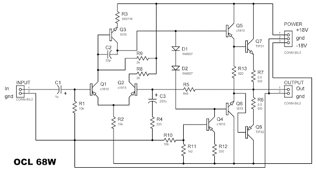
OCL 68 Watt Power Amplifier
The power amplifier has the power output up to 68Watt. Is compared with the power amplifier circuit LM386, OCL circuit can be 50-100 times more powerful (produce sound louder). Of course to be able to produce a good sound is needed Speaker and the corresponding symmetrical PSU as follows:
Speaker: size 6-12 inc, impedance 4 ohms and above 68Watt
PSU symmetrical: CT transformer 18Volt 3A.
Circuit diagram and pcb layout OCL 68 Watt Power Amplifier :
There is one red colored line above is a jumper picture PCB track
List of components: (in brackets is the name ddalam footprint search for software proteus ares)
Component List OCL 68 Watt Power Amplifier:
Input: To control jack connected audio / tone / mp3 player module.
- "+ 18 gnd -18": obtained from a series of symmetrical PSU. voltage power does not have to + 18-18 + 12-12 volts but given or + 15-15 volt also be able to produce sounds pretty good
-output: connected to speakers
- Cooler
At work, this circuit transistor Q7 (TIP31) and Q8 (TIP32) severe enough to produce a fairly high heat. Therefore it takes mounted cooler to help distribute the heat of the transistor. Installation of cooling should be because the second transistor may not connect by cooling. if so there will be a surge and damage the transistor. it is necessary insulators.
Circuit diagram and pcb layout OCL 68 Watt Power Amplifier :
There is one red colored line above is a jumper picture PCB track
List of components: (in brackets is the name ddalam footprint search for software proteus ares)
- Plain PCB
- Solvent PCB
- Cables (red, black) to taste.
Component List OCL 68 Watt Power Amplifier:
A brief discussion:
- R1: 10k (RES40)
- R2: 15k (RES40)
- R3: 100 ohm / 1W (RES50)
- R4: 220 ohm (RES40)
- R5: 6k8 (RES40)
- R6: 0,5 ohm / 5W (RES90)
- R7: 0,5 ohm / 5W (RES90)
- R8: 2k (RES40)
- R9: 2k (RES40)
- R10: 10k (RES40)
- R11: 1K2 (RES40)
- R12: 330 ohm (RES40)
- R13: 820 ohm (RES40)
- C1: 1uF / 16V (ELEC-RAD10)
- C2: 33pF (CAP20)
- C3: 220uF / 16V (ELEC-RAD25M)
- Q1, Q2, Q4, Q5: c1815 (TO92)
- Q3, Q6: 1015 (TO98)
- Q7: TIP31 (P1)
- Q8: TIP32 (P1)
- D1, D2: 1N4007 (DO41)
Input: To control jack connected audio / tone / mp3 player module.
- "+ 18 gnd -18": obtained from a series of symmetrical PSU. voltage power does not have to + 18-18 + 12-12 volts but given or + 15-15 volt also be able to produce sounds pretty good
-output: connected to speakers
- Cooler
At work, this circuit transistor Q7 (TIP31) and Q8 (TIP32) severe enough to produce a fairly high heat. Therefore it takes mounted cooler to help distribute the heat of the transistor. Installation of cooling should be because the second transistor may not connect by cooling. if so there will be a surge and damage the transistor. it is necessary insulators.


now am trying to learn how to make an amplifier i like this site thank u
ReplyDeleteThe transistors 2SC1815 are drawn as PNP in the circuit diagram, but they are NPN. The transistors 2SA1015 are drawn as NPN, but they are PNP. right?
ReplyDeleteno its reverse wrong scheme
Delete