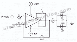
Polarity indicator circuit
Is is easy to test the polarity of a circuit’s point whether it is positive or negative by using the tester circuit featured here. The tester circuit has a high input impedance (around 1 megaohms) to avoid loading the point being tested. In testing sensitive points however, (inputs of opamps), the input impedance must be taken into consideration.
The opamp 741 is the core of the polarity indicator circuit. Its non-inverting input is used to test the points for polarity. It has a gain of around 150 which enables it to test low voltage levels. The test result is displayed through the two LED’s D1 and D2. D1 lights up by positive polarity and D2 lights up by negative polarity. Take note that the pin profile on the diagram is based on the TO-5 package profile.
.jpg)

Post a Comment for "Polarity indicator circuit"
Dont use outgoing links!